
From: "Hedwig Poon" (hedwig.poon@encompass-tech.com)
Sent: Friday, September 15, 2000 6:09 PM
I was looking @ the wires to cut diagram and trying to match up what part the ECU controls and it doesn't make sense. First, the digram between the instruction and the Mazda manual is reversed, so I counted pins backwards to match. If that's the case, the connectors are 4, 3, 2, 1 on the instruction leaflet. But the pin assignments have me perplexed. On the diagram, it seems they are telling us to remove the following:
4V - Precontrol Solenoid Valve Output
4L - Oil Metering Pump Stepping Motor Output
4K - Oil Metering Pump Stepping Motor Output
3H - Purge Control Solenoid Valve Output
This is based on the instruction being a complete mirror image of the manual. (ie. connector 1 on the right on leaflet, connector 1 on the left in manual, with pin 1U as the top right pin on leaflet and 1U as top left pin in manual. It doesn't make sense...
However, if we keep the connectors mirrored but the pinouts as per manual (ie. pin 1U is top left on leftmost connector in manual but is top left on rightmost connector on leaflet), things make more sense. Having said this, wonder if we can disable these items in the Commander instead of snipping wires....hmmmmm.
4F - Split Air Bypass Solenoid Valve Output
4O - EGR Solenoid Valve Output
4P - AWS Solenoid Valve Output
3J - EGR Switch Input / DRL Input (Canada)
The concern is now the above would indicate definitely emission testing issues. The AWS is not required for most but the split air is for the main cat - right? - and the EGR is for cleaner emissions.
_________________
Date: Fri, 15 Sep 2000 21:55:55 -0700
From: "Matt Ledbetter" (matt_ledbetter@netzero.net)
I thought the diagram was backwards as well.... The diagram is looking at the connector from the back (i.e. where the wires go in to the connector).
Here is a snip from a message I sent a few weeks ago...
Also, for future reference or FAQ, here are the wires that need to be cut: Assuming that the FC is mounted with Apexi logo out. Top connector: blue w/ yellow stripe, brown w/ yellow stripe, and black w/ red stripe. 2nd connector: This one is hard to identify on my car, but it looks like blue w/ dark blue stripe. Of course, verify all of these with the included Apexi diagram as the harness *may* be different from car to car.
Hope this helps... I plan on throwing the stock ECU back in and connecting the wires for the smog test...
__________________
Date: Mon, 19 Mar 2001 14:42:55 -0800
From: "Attila Fisher" (atihun@home.com)
DO NOT CUT THOSE WIRES!!!!!!!!! THEY ARE BACKWARDS ON THE MANUAL!!!!!!!!!!!!!!!!!!!!!! WARNING!!!!!!!!!!!!!!!!!!!
Ok, now that I have your attention, the wires that need to be cut control the EGR valve, the Accelerated Warmup System, and some other smog related stuff.
Make sure that you are looking at the wiring harness correctly. If you still have a problem with them, email me.
________________
Date: Mon, 19 Mar 2001 18:54:44 -0600
From: "Forrest Royder" (black94rx-7@cox-internet.com)
> So just out of curiosity, has anyone tried using the PFC *without* cutting
> any wires at all? Granted most of that stuff (AWS, EGR, split air bypass,
> etc.) you really don't need, but what happens if those wires are not cut?
> Does that cause the ECU to choke?
I drove around the block with all the wires attached...not pretty. The transition from open throttle to closed throttle was VERY harsh, and the car tried to idle at 3k. Wires cut, everything normal.
_________________
Date: Tue, 20 Mar 2001 09:34:12 -0800
From: Michael_Broadus@digidesign.com
I did not cut the four wires initially when I installed the Power FC. Basically from what I could tell, electrical load was always on, you can check it in the "etc" menu on the PFC. So great, built in fan mod right? But, when starting it up warm, it would rev to about 2k RPMs, drop, rev to 2k, drop and over and over from 3 to 10 times. I finally got tired of it and clipped the wires, its been fine ever since. Other than that I didn't notice any issues with the way the car performed, it ran the same before and after clipping the wires.
_________________
Date: Tue, 20 Mar 2001 09:37:43 -0800
From: "Sam Tarbox" (Sam.Tarbox@xilinx.com)
The boxes that come from Shane Racing don't need the wires clipped, or so Ray told me when I got mine. He says he does something to the programming that doesn't make the clipping necessary (I never clipped any wires and mine works fine). I think the wires only need to be clipped when you buy a box "untuned" from another vendor or something, but I can't say for sure.
__________________
Date: Wed, 21 Mar 2001 10:02:36 -0800
From: "Mark Peters" (mpeters@transmeta.com)
You do NOT need to cut any wires when ordering from SR. If you look at the box, Ray has pulled the pins out of the unit so they do not make connection. This was the option he used instead of making his customers cut any wires and possibly cut the wrong ones.
__________________
Date: Tue, 13 Mar 2001 18:05:52 -0500
From: Erik Hjortshoj (ech@mindstorm.com)
Subject: (rx7) Power FC Boost Control - Very Long
I think an understanding of the wastegate is an important part of understanding the PFC settings. I hope this posting will help some people. I tried to gather as much fundamental information as possible to provide a good foundation, but did not come up with a lot of stellar observations. If you don't care to read a lot about the turbo control system, skip to the end. If you see any mistakes, please send me any corrections.
- -------------------------------------------------------
How the Stock Wastegate Control Works
- ----------------------------------------------------------
The crude diagram below is an ASCII interpretation of the excellent diagram at the Rob Robinette site.
This is only the wastegate control diagram. The PFC also controls the turbo precontrol actuator, but since it doesn't give us any settings there is nothing for us to consider. It probably does something pretty close to what the stock ECU does.
    |Prim.|     |W.Gate|       | ECU |
(1) |Turbo|     |  __/ | (5)   |     | (9)
       |          /||             |
       |           ||             |
    |Pill|-->--| W.Gate |-->--| W.Gate |--> Vent
    |    |     |Actuator|     |Solenoid|

     (2)   (3)    (4)     (6)     (7)       (8)
The PFC is similar to the stock ECU. It also uses the duty cycle of the wastegate actuator to control boost, under the same principles.
So for both stock and PFC ECUs:
These are just relative relationships - Mazda seemed to figure out maps that would predetermine the duty cycles to get what we have. It's easy to see how the balance could be tipped by component changes or failures.
Many people change the pills, or use adjustable valves to change the max rate of flow into the actuator. A larger pill orifice has the approximate effect of reducing the duty cycles across the entire map. A smaller pill orifice has the approximate effect of increasing the duty cycles across the map. The PFC gives us some control over the boost levels that may also have a global effect on the duty cycle maps. For both of these there seems to be some side effects that should be mentioned.
Smaller Pill and/or Higher Overall Duty Cycles Give:
Conversely a Larger Pill and/or Lower Overall Duty Cycles:
=======================================================
Tuning Boost on the Power FC
- --------------------------------------------------------
What We Know:
Pages 27 and 28 of the American Power FC manual have some instructions for tuning boost, and there is some info there, but there are as many open questions. Here is a summary of what seems to be clear:
The maps in the manual are:
1. Pr 0.80kg/cm2  56%
   Sc 0.70kg/cm2  64%
2. Pr 0.90kg/cm2  62%
   Sc 0.80kg/cm2  70%
Here Goes a Lot of Speculation:
The PFC uses the stock engine inputs, their maps, the configuration settings above, and some dynamic "learning" algorithms to control boost through the duty cycle of the wastegate. This is important because both the "boost level" and "base duty" in the boost setting page have to control the same thing - the duty cycles at any given time. The boost setting also controls fuel cut. When adjusting desired boost you should be adjusting both the desired level and the base duty values for best effect. The manual states this as well, but is not clear on how to do this.
If you adjust for a lower boost level and do not lower the base duty then you can get the fuel cut! I was told (have no confirmation) that fuel cut in the PFC is actually ignition cut - so it may be safer, but it is still not good. If you have a base duty number that is too low, you will probably not get the desired boost levels consistently, if at all.
In my car I found it best to extrapolate from the settings in the manual, with about 6% base duty for each 0.10 of boost. When I had lowered boost by 0.10 or more without lowering base duty I would get fuel cut on transition in cold weather. YMMV.
That's about it:
- ----
Mysteries:
As always - be super careful tuning and ECU - since it can
blow up your engine.
As always - be super careful while testing your vehicle!!
_______________
Date: Wed, 14 Mar 2001 08:54:48 -0500
From: "Wade Lanham" (wadelanham@hotmail.com)
>8) Vent.  Where the air goes is not important (but does
>   anyone know?).  What is important is that it reduces
Air goes into the metal manifold that runs approximately from the wg/pc solenoids down to the primary turbo inlet. Both of the solenoids (wg + pc) are vented back into the primary intake elbow.
________________
Date: Tue, 13 Mar 2001 16:55:42 -0800
From: "les" (lesd@earthlink.net)
Here is my theory on how and what the PFC learning is about: The base duties are something you can set to give the learning algorithm a 'head start' in it's self tuning. It starts using those values first, then if it sees the boost go too high, it can modify the value to make it better.
The big question is how fast is the so called 'learning'? Is it just like other electronic boost controls, that are 'closed loop' and respond in real time to keep things limited. Or did they use something that takes a few tens of boost hits to tune the numbers, letting the engine spike until it got the numbers right. Yuk!
Boost controls that respond too fast can flutter the boost level, because there are slight time delays associated with the duty cycle changing and the actual boost change. A 1/4 second too late, and it starts going too high. Then it reacts by changing the value too much, and now it's too low, and again, and again.... you see the cycle. Boost controllers that have smarter 'brains' can see the flutter and back off the gain by themselves.
The twin turbo stuff makes things even harder, all kinds of spikes to be aware of during the transitions from one turbo to the other. In my case I have just ignored the whole solenoid thing, an connected the wastegate to the manifold, giving me a rock stable but non adjustable setting. The single turbo is a bit easier to deal with than the twins, I might add.
_______________
Date: Mon, 03 Jun 2002 00:02:20 -0500
From: Phil (johnalla@swbell.net)
Subject: RE: (rx7) [3] AC problems
    > Has anyone ever had weird problems with their HVAC fan switch and their AC?
    > The fan switch controls the fan speed properly.  The LED in the AC switch
    > works properly.  However, if you have the AC switch on, the AC only works
    > with the fan set at 1, and sometimes works on 2, 3, and 4.  Sometimes it
    > will flicker on and off in settings 2, 3, and 4.  I can verify all this via
    > the PFC sensor check.  Jiggling the fan switch has no effect.  I'm planning
    > to go through the AC section in the shop manual but was wondering if anyone
    > had seen this before.
After a little searching the forums, it looks like this is a PFC problem and I have been living in the dark. Chuck Westbrook posted these instructions:
------------------------------------
I claim no responsibility or liability for anyone who follows my instructions. You are solely responsible for any changes you make to your car. Do not attempt this if you are not experienced with wiring.
Following is details from the manuals and how to make your AC work with the PFC. Three ECU AC functions will be lost with this conversion. If the AC is on, it will not be temporarily disengaged when starting the engine. When accelerating hard, the AC will not be temporarily disengaged. The idle speed will not increase when the compressor comes on. The AC will function normally with all AC components working, except with no ECU control.
Reference materials:
BEM page G-12 AC wiring schematic:
At the left side it shows the AC compressor wiring;
+12V - ignition/acc switch - AC fuse - AC relay - AC pressure switch - AC magnetic
clutch - ground. From the relay control coil is a Y/B (yellow with black strip)
wire that goes to the ECU. It is marked as connecting point 37 and continues on
the WSM B-1d schematic. On WSM B-1d, point 37 goes to ECU connector 1L. The ECU
basically grounds out this connection to energize the AC relay to turn it on.
In the middle of BEM page G-12 it shows the AC control wiring; Ground - fan speed switch - AC switch - AC thermal (anti freeze) switch - and a wire colored V (violet) going to the ECU. It is marked as connecting point 36. On WSM B-1d, point 36 goes to ECU connector 1E. The ECU basically senses ground through this wire when you turn on the AC.
Cut the two wires at ECU terminals 1L(Y/B wire) and 1E(V wire). This is the bottom connector with 11 pin columns. 1L is the center pin opposite the connector lock tap. 1E is third from one end. Connect the harness side of them together thus bypassing the ECU. Leave the ECU side open. I placed snap-in connectors on all four wire ends so that they could be easily reconnected back to stock.
The cooling fans are operated from another wire that attaches to the AC relay and is not affected by this mod. In fact if you turn on the AC with the two wires cut but not connected together, the fans come on but nothing else happens. The ELU unit will still increase idle speed a little when the fans are turned to 3 or 4.
______________
Date: Fri, 11 Aug 2000 16:32:35 -0500
From: "Westbrook, Chuck E." (CWestbrook@tmh.tmc.edu)
The Power FC and Commander use the overheat light as a warning whenever a sensor is having problems! That is what the Commander manual states. So keep that connected.
______________
From: Travis (greys@peoplepc.com)
Date: 12/06/2001 11:29 PM
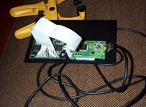
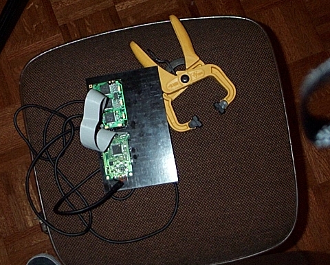
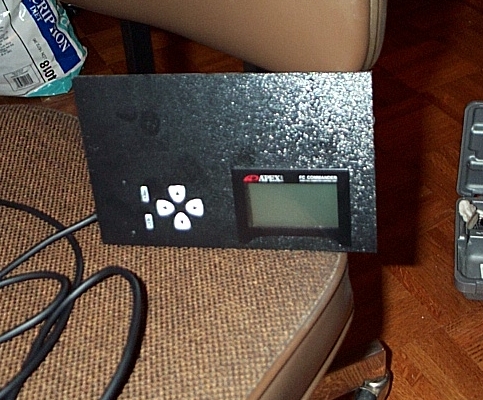
I took my PFC commander apart and used some 20 pin ribbon cable to reattach the two pieces.Ā I then took a piece of standard 12X12 plastic from a stereo install shop and custom cut the holes for the screen and the key pad.Ā I attached them using aĀstandard epoxy and covered the screen cut with the face of the commander.Ā I have it installed in my car using four zip ties until I buy my new stereo but I don't think it looks too bad just the way it is.Ā

![[ Mail me ]](mail.gif)
![[ To Lightning home page ]](rx7_home.gif)
![[ To my home page ]](my_home.gif)
![[ Copyright Notice ]](copyright.gif)