
![]()
_______________
The following write-up and photos were done by
Anthony Bulger. Steve Kan emailed them to
me. I added a few links to other
sections of my site for procedures on some of the steps Anthony has listed. Steve sent
me a Word file which I modified into HTML. The file had "Sequential" in the filename,
so these instructions probably apply to a sequential turbo setup (stock), so there may
be differences if you are going to install a Haltech on a non-sequential twin turbo or
a single. --Editor.
________________
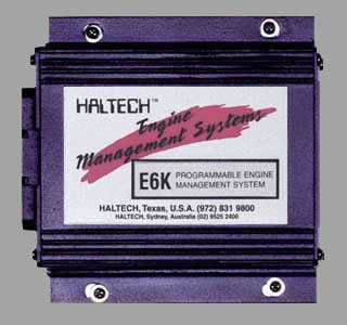
From: Anthony Bulger, by way of Steve Kan Below are the steps that I took to install my Haltech E6K into my 93 RX-7. These are
in no way the "Complete" instructions for installing the E6K. I have provided information
that I believe is correct and accurate. However there may be mistakes in these notes
that can cause damage to your car. Any steps you take are your choice! None of the people
listed in this document are liable for you choosing to perform any of these steps. We are
only trying to provide help and information. Please remember to take time to perform any
and all repairs to your car in a safe and wise mannor.
Before you start your install take the time to read and familarize yourself with
the Haltech manual. The manual will describe how everything works on the unit and will
describe the install process for the basic unit. I suggest you borrow or buy a Workshop
Manual for your year model. Make yourself a clean workspace. Get some paper and a pencil
as well as a camera so that you can notate any steps you've made for future reference.
The install should take several hours and probably can be done in a day if you have
some experienced help. I took my time and spent 2 weeks on mine. I also performed some
other Mods at the same time which slowed my process somewhat. The install is really
not that bad however you will be somewhat overwhelmed at times. Trust me this is normal
even for the pros. If you are unsure of yourself PLEASE let a professional tuner
perform the install and Tunning process. This will quite possibly save you a popped motor.
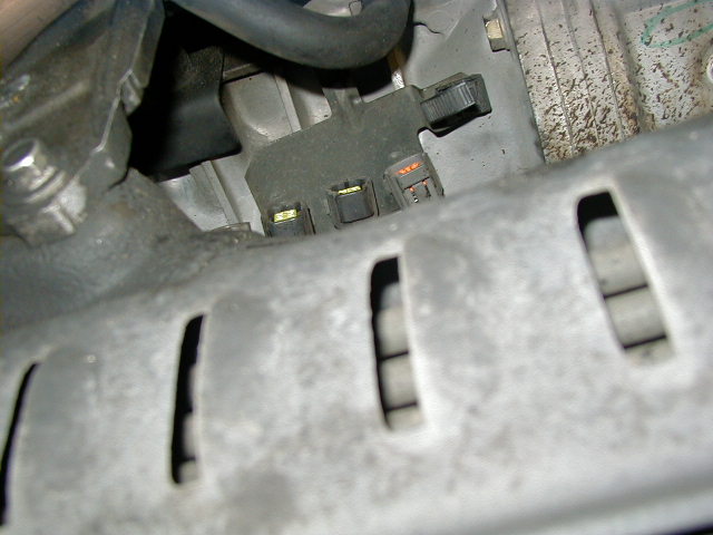
This is a good time to change plug wires
or even do an Ignition Mod. With the Coil Rack removed you will see more of the ECU's
harnesses here to remove. I believe there is a grounding bolt as well as the connections
for the Water temp, Knock Sensor and, Oil Pressure sensor. I do not believe you have
to disconnect the oil pressure connections. If you are feeling daring you can remove
the Solenoid Hose rack. You will have to reroute these hoses for the Haltech anyway
and you can use this opportunity to clean this area as well as do a silicon hose
replacement. Warning! These hoses tend to be hard and brittle. The solenoids will
also be brittle. It is easy to salvage these if you take time and patience. One
trick I have learned over the years is to take a small Butane Torch and heat the hose
till it starts to smoke. Let it cool for a second or two then gentle twist and remove.
The hose may make a snapping noise when it breaks free. This is normal. Below is a
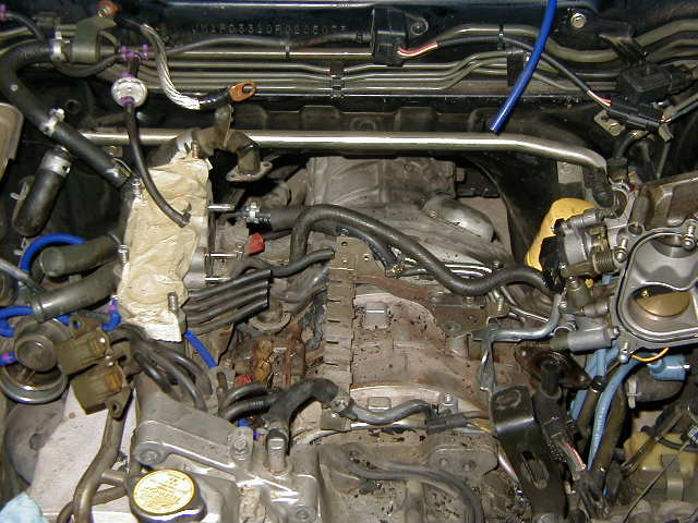
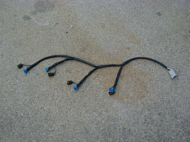
photo with the Manifold, Solenoid Rack and, Coil Rack removed.
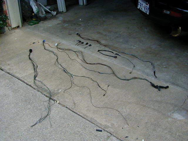
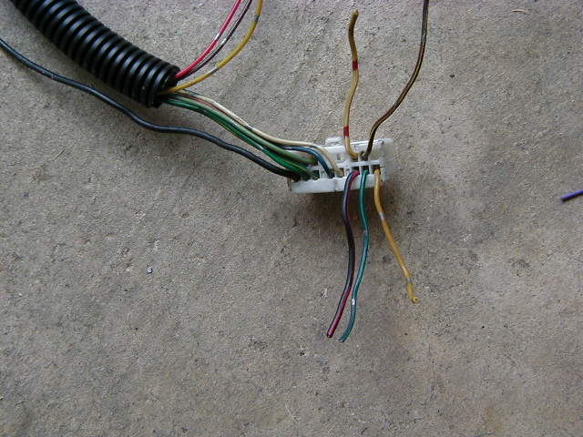
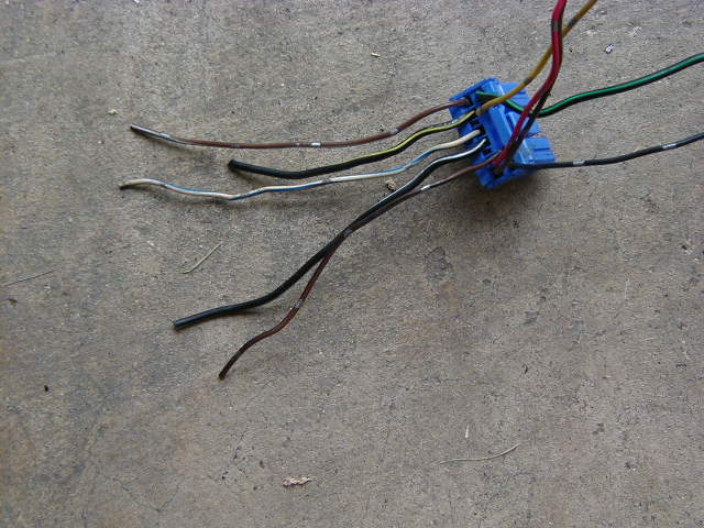
Note: Cut the following wires below w/ approx 5-6" of length for possible future
solding. (in case we might need them afterall).
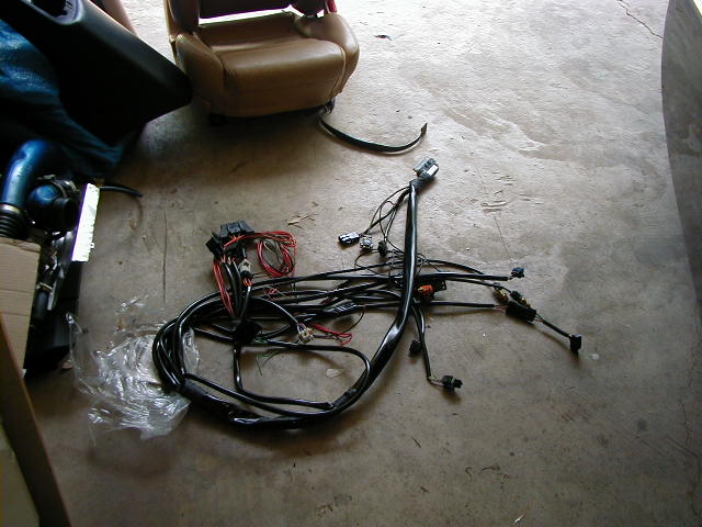
Now your harness should be ready for install. Just reinstall following the removal instructions.
Leave the motor torn down for the moment.
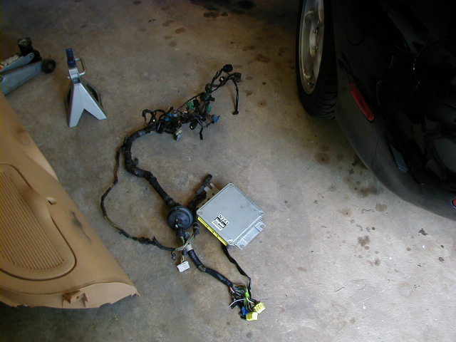
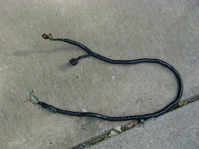
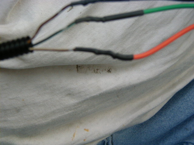
The following photo shows the Haltech terminated harness. I want to end this with some thank yous! I want to Thank Chris, Ari, and Solo from
Rotary performance. For whom whose help and tunning was cruical in the rebirth of my rex.
I want to thank Steve for helping in the install and pointing which wires to and not to
cut. I also want to thank Steve for helping me get the car running enough to drive her
to RP for final tuning. I need to put in a thanks to my neighbors for not complaining
about the Backfires and Fireballs I shot driving up and down the street when we were
tuning. That guy driving the mustang we passed is probably still tramatized from the
fireball I shot out the talepipe when passing him. Oh and let's not forget Steve
figiting with the laptop cord because the battery was dead, we stopped at Sonic to get
a coke and the fuel map got erased. I'm thankful he was well versed in the programing.
_________________
From: Jay Hanacek (Styk33@ricemobile.net) I looked at most of the EMS (Engine Management Systems) before purchasing
the Haltech E6K. I found the Haltech to be the best bang for the buck and it
had all the features that I needed for what I wanted the Ricemobile to be
capable of. I looked at Wolf, Electromotive, MoTeC, Apex and the PMC. All in
all, the MoTeC was by far the best, and the Apex Power-FC was the most
restrictive.
After getting the box in the mail I thought I had bought something that I
could not install. There were a lot of wires and a 150-page manual. After
reading threw the manual and looking at each part of the system that needed
to be install, I realized it is not all that bad. If you can install an
alarm with power window and remote start the Haltech is easy.
There are about 20 wire connections that need to be made. I left my main
engine wiring harness in and wired the E6K to the wires going into the stock
ECU harnesses. With those simple connections made it was on to pull some
wires threw into the engine compartment. There are three sets of wires that
needed to be in the engine bay. Three wires for the MAP sensor, two wires
for the coolant sensor, and two wires for the air temperature sensor.
Once the wires are in the engine bay you need to mount the MAP sensor. This
can be mounted were the stock Mazda one was since you don't need that one
anymore. As long as it is mounted above the top of the lower intake manifold
you are fine. The idea is to keep the fuel from being siphoned into the
sensor.
Then you need to tap and install the air temp sensor. You have a couple of
choices for this. You can mount it in the stock location like I did. Or
drill and tap a new hole for it and keep the stock sensor so you can go back
to stock easily.
The next sensor is the coolant sensor. I installed mine on the back of the
water pump, where the Mazda thermo sensor was. That sensor already had a
hole big enough for me to just stick my tap in and start tapping, instead of
trying to fit a drill in there with the water pump on. The hole that I used
is the lower of the two sensors and took about 30 minutes to tap due to its
location.
The two major connections that need to be made that don't connect to the ECU
harnesses are for the power and ground. Run the ground to the battery or a
good chassis location. The positive wire should go straight to the battery.
There are many options to connect the fuel pump. I connected one of
Haltech's fuel pump wires to constant power and the other one to the
white/red wire under the master cylinder. That wire goes straight to the
fuel pump without any relays interfering. This also allows you to disconnect
the factory fuel pump resistor (looks like a little heat sink). The Haltech
has a relay that controls when the fuel pump gets power, so my fuel pump is
not running all the time so connecting to the batter is fine.
After all that work, I loaded up my base map and checked all the sensors and
started the car. It started up after a few seconds, due to my tiny battery.
After playing with the maps and stuff for a few days straight, I have made
my car run nice and smooth for the most part. A lot better than the M2 ECU I
had in there. Not that, that ECU was bad, just different.
And for all the folks that say there gauges don't work or the A/C, cruise
control, power steering, sequential turbos, turbo timers and whatever other
BS you can think of. All my gauges worked fine with only one wire I had to
hook up additional to the E6K. My A/C worked (for about two minutes, then I
tore it out). My cruise control works and everything else. I used the stock
TPS, stock coils, and igniter. I also used the internal reluctors on the
E6K. The stock MAP, coolant and air temps sensors can also be used. Keep in
mind that the stock MAP is only good up to 2 bar (~15psi), so if you want to
run more boost you need the 3 bar (~30psi) sensor from Haltech.
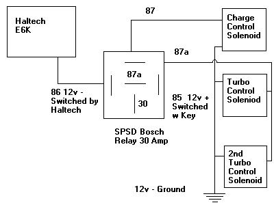
The E6K has some additional outputs to control extra goodies. You can
control when the radiator fans turn on and off. There are other features
like, sequential turbo control, IC fan, shift light, turbo timer, NOS
controls, boost control, and for those of you crazy guys out there anti-lag.
It also has a flat shift and a 2-step ignition available for you drag
racers.
I have also got rid of my Apex AVC-R and am running the Haltech
solenoid/boost control. The Haltech boost controller works the same as the
AVC-R just not all the fancy lights that I didn't like. The thing that the
Haltech controller lacks is the fuzzy logic and a gear adjustment for boost.
Since your load is increased in higher gears you are more likely to build
more boost. This means I hit the boost cut (not fuel or ignition cut) on the
Haltech boost controller in 5th gear. I plan to go back to the AVC-R in the
future, but until then, the Haltech controller is good. If you never went to
a stand-alone boost controller before upgrading to the Haltech you can
utilize this feature in the Haltech and save some money.
Tuning Hints and Stuff
A little advice on some situations I have had with my car. If you car takes
a long time to start compared to the factory ECU during cold winters you can
enrich you coolant correction map threw all levels below 60F. This helped my
car immensely for starting. Since your car runs no cooler than 150F when
actual driving this will not effect the car except under starting conditions
and part of the warm-up. I also added fuel to the 0RPM range since the
Haltech pulls from that map during starting.
Remember to keep the gap between the primary and secondary fuel injectors
the same level all the way threw the RPM range. Otherwise you will have a
stumble when you get on boost. The change over on my maps is setup to happen
at around 1psi. The way to tell were it is happening is by looking at the
bars, the primary injectors are shaded and when the primary and secondary
injectors are on, they are just blank bars.
I have leaned out a lot of the extreme vacuum areas (>22psi) since they are
not normally scene during cruising and only during shifting. Since doing
this I don't have any unburned fuel igniting in the exhaust causing
fireballs. Flamage is an attention getter at the drag strip, but that is not
what I am going for. Be careful not to lean these sections out too much. If
you do, then under light cruising throttle you will have surging due to the
lack of fuel.
I am planning on putting up some different maps of different engine setups
in the near future. Stock turbos stock fuel, along with upgraded fuel and
T-60, T-66 and the T-78 turbo. Of course these maps will only be a baseline
for someone's car since all setups are different.
If you have any questions, please email me or ICQ me. If I don't have the
answer there are a couple hundred of us Haltech owners on Yahoo Groups at
'Haltech-Support' that might be able to help.
Here is an older version of the previous post, in case there is anything here that is
not included with Jay's original post. --Editor.
From: Jay (styk33@yahoo.com) I bought and installed my E6k a couple weeks ago. I have been getting email and phone
calls about it in the past couple weeks. So I figured I would post something for those of
you that to shy to ask questions
After getting the box in the mail I thought I had bought something that I could not install.
There were a lot of wires and a 150 page manual. After reading threw the manual and
looking at each part of the system that needed to be install, I realized it is not all that
bad.
There are about 20 wire connections that need to be made. I left my main engine wiring
harness in and wired the E6K to the wires going into the stock ECU harnesses. With those
simple connections made it was on to pull some wires through into the engine compartment.
There are three sets of wires that needed to be in the engine bay. Three wires for the
MAP sensor, two wires for the coolant sensor, and two wires for the air tempature
sensor. I also connected my fuel pump wire in the engine compartment instead of using
the stock relays like other. So that adds another wire that need to be pulled through the
firewall.
Once the wires are in the engine bay you need to mount the MAP sensor. This can be
mounted were the stock Mazda one was since you don't need that one anymore.
Then you need to tap and install the air temp sensor. There are two places that you can
do this. One is on the upper intake manifold and replace the stock one. This is where I
put mine. You could also do what someone else did and leave your intake manifold on and
tap your intake elbow. This will put the temp sensor before the TB instead of after. It
also puts it off to the side of the motor instead of above it. Not the best spot, but would
work for a temporary weekend install if you want to leave your UIM on.
The next sensor is the coolant sensor. I installed mine on the back of the water pump,
where the Mazda thermo sensor was. That sensor already had a hole big enough for me
to just stick my tap in and start tapping, instead of trying to fit a drill in there with the
waterpump on.
The two major connections that need to be made that don't connect to the ECU
harnesses are for the power and ground. Run the ground to the battery or a good chassis
location. The positivie wire should go straight to the battery.
My fuel pump connection was the confusing to some people, but simple in my mind and
others that helped me. This was the one problem that I had when my car wouldn't start. I
tried to use the stock relays and that didn't work. So I connected one of haltech's fuel
pump wires to constant power and the other one to the white/red wire under the master
cylinder. That wire goes straight to the fuel pump without any relays interferring. The
Haltech has a relay that controls when the fuel pump gets power, so my fuel pump is not
running all the time.
After all that work, I loaded up my base map and checked all the sensors and started the
car. It started up after a few seconds, due to my tiny battery. After playing with the
maps and stuff for a few days straight, I have made my car run nice and smooth for the
most part. A lot better than the M2 ECU I had in there. Not that, that ECU was bad, just
different.
And for all the folks that say there gauges don't work or the A/C, cruise control, power
steering, sequential turbos, turbo timers and whatever other BS you can think of. All my
guages worked fine with only one wire I had to hook up additional to the E6K. My A/C
worked (for about two minutes, then I tore it out). My cruise control works and
everything else. I used the stock TPS, stock coils, and ignitor. I also used the internal
reluctors on the E6K.
The E6K has some additional outputs to control extra goodies. You can control when the
fans turn on and off. There are other features like, sequential turbo control, IC fan, shift
light, turbo timer, NOS controls, boost control, and for those of you crazy guys out there
(Eric) anti-lag. It also has a flat shift and a 2 step ignition availible, but I have not got
these to work yet.
All in all I am very happy with my purchase. I plan on running the Haltech boost control
next month and I will report back on what that is like compared to my AVC-R.
If I missed something or anyone has some questions I will try to help. I know there are a
couple of you out there that have E6Ks and might have some other input.
________________
From: Mike Ack! Let me quote you to get it right:
Heh, Jay is refering to me. I stuck that damn sensor right in my Greddy elbow. I believe it
works great. I have seen no draw back. But, as Jay says its not inside. But, I use this
sensor to determine what my air intake is from the IC. The one inside will do the same,
but, it will prolly rise a degree or 2 due to the extra metal.
Anyhow, thanks Jay! hahaha.
Haltech Installation
Date: September 18, 2000
Tools and Supplies:
Procedure:
Date: April 4, 2001
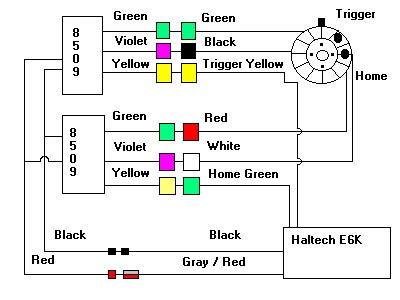
RX-7
Harness to E6K Harness
E6K
Conn
Description
4E
Yellow
Yellow
J16-B
Crank NE +(Trigger)
4H
Red
Red
J16-C
Crank NE -(Input A)
4H
Red
Blue
J16-D
Crank G -(Input B)
4G
White
Green
J16-E
Crank G +(Home)
4W
Lt. Green/Red
Lt. Blue
J13
Injector 1 (Primary)
4Y
Lt. Green/Black
Blue/Red
J13
Injector 2 (Primary)
4X
Lt. Green/White
Green/Red
J13
Injector 3 (Secondary)
4Z
Lt. Green
Pink
J13
Injector 4 (Secondary)
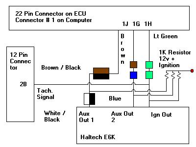
1G
Brown
Blue
J7
Front Igniter (Digital Out 2)
1J
Brown/Black
White/Black
J7
Rear Igniter (Digital Out 1)
1H
Lt. Green
Lt. Green
J7
Leading Igniter (Igniter Out)
1T to 1K
Orange
Flying
Fuel Pump Relay (Connection 1)
Connect to
Chassis (-)
Orange
Flying
Fuel Pump Relay (Connection 2)
Connect to
Battery (+)
Red
Flying
Main Power
Connect to
Chassis (-)
Black
Flying
Ground
1B
Black/White
Gray
Flying
Ignition Power
3D
White/Blue
Violet/White
J18
PWM1 (Radiator Fans)
4Q
Lt.Blue/Green
Pink/Black
J18
PWM2 (BAC)
1L
Brown/Black
Blue/Green
J18
PWM3 (A/C)
2J
Gray
Green/White
J18
PWM4 (Air Pump)
3C
Black
Gray
J6
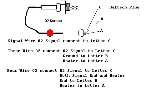
O2 Sensor
1M
Green/Red
Gray/Yellow
J17
Road Speed
4D
Brown/Black
Black
J10-A
TPS (-5V)
3G
Black/Green
White
J10-B
TPS (Signal)
3I
Brown/White
Orange
J10-C
TPS (+5V)
3L
Green
Gray
J11-B
Air Temp Sensor
3E
Green/White
Violet
J12-B
Coolant Temp Sensor
Stock ECU to
Stock ECU
1H
Lt.Green
2B
Yellow/Blue
Tachometer Signal
1T
Blue/Black
1K
Blue/White
Connect these to Fuel Pump Relay
Date: August 12, 2000 12:11 AM
Date: August 17, 2000 01:46 AM
>You could also do what someone else did and leave your intake manifold on and tap your
>intake elbow. This will put the temp sensor before the TB instead of after. It also puts it
>off to the side of the motor instead of above it. Not the best spot, but would work for a
>temporary weekend install if you want to leave your UIM on.

![[ Mail me ]](mail.gif)
![[ To Lightning home page ]](rx7_home.gif)
![[ To my home page ]](my_home.gif)
![[ Copyright Notice ]](copyright.gif)