

From: Teddy Wang (f2racer@covad.net)
06/28/2001 07:00 AM
|
How to Change an FD's Spark Plugs and Wires: |
|
Well I got brave after getting laid off last week and decided to change the spark plug and wires on my 1993 Mazda RX-7. I'm actually starting to get pretty good at wrenching my rex... Especially since before this last year that I've spent with 2 rexes, I've not really done too much wrenching and when I have it's on my 1994 Ford Mustang GT which has a 302 and lots of room under the hood which makes most tune-up stuff pretty easy. OK let's get on with the story. Total time it took for me to get everything apart and put back together was approximately 3 hours. Probably would have taken me a third the time if I'd done it before. And it probably would have taken me two to three times longer if not for the great information that I found on Rob Robinette's and Steve Cirian's sites. The only funky tool I needed was a 3/8" flexy head ratchet, and that was for getting the plugs on and off. There's very little room once you get down to where the plugs actually are and the flexy head will allow you to turn the ratchet more so that you won't have to guess when you've turned the plugs 1/2 turn... |
|
| First things first. Gotta get your plan of attack. I opened the hood and almost automatically gave up. Although the info that I found was very helpful, looking a FD's engine bay could make any mechanic cry. To date, I've done some vacuum tube diagnostics by myself. I've even removed the stock airbox and gotten down to where the vacuum tubes with the pills are, but that was child's play compared to what I was about to embark on. | 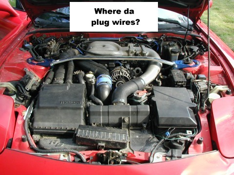 |
| The plugs and wires require you to disassemble 3 major components from your automobile. The intake elbow is fairly straight foward. The throttle body is a bit more difficult. And the oil filler neck is pretty straight forward. First to address the intake elbow. There's a hose (air I guess) is connected to the back of the elbow. This must be disconnected. Also you've got to disconnect the hose that connects the elbow to the intercooler. There are 4 x 10mm acorn nuts that hold the intake elbow on. Remove them and the intake elbow slides off easy. | 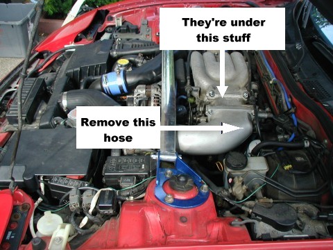 |
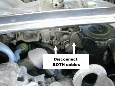
| Next you've gotta prepare the throttle body to be
removed. There are 2 cables which need to be disconnected (one also
has a mount that needs to be disconnected from the throttle body) as well
as a coolant hose.
One cable runs along the intake manifold and is the most evident. The second goes to the throttle body from the drivers side of the car. Just push the springs back and release the cables. |
 |
| The coolant hose is almost directly underneath the throttle body. As long as you can position the clamp so that you can get pliers on it, you should be all set. If the hose is really stuck, twist it before trying to pull it off. Also pulling the hose will result in all the coolant in the throttle body coming draining out. Be careful of how hard you pull to minimize splashing. You could also remove the coolant hose at the rear of the throttle body as well, but as you'll see it's unnecessary. | 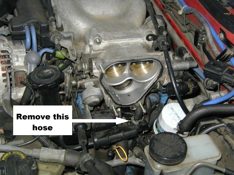 |
| Throttle body removal time. Remove the 4 x 12mm acorn nuts that hold on the throttle body. Gently pull the throttle body away from the intake manifold. Be sure to use care as there's a gasket that sits between these two parts, which you probably want to reuse. Also use care as when you pull the throttle body off, it's likely to leak some more coolant. Once the throttle body is off, you should have a little bit of play (if you did not disconnect the rear throttle body coolant hose), use this to rotate the throttle body ontop of the intake manifold. Be sure to put down a cloth prior to putting the throttle body down. | 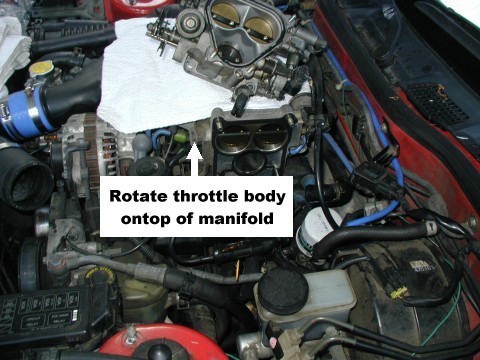 |
| Remove the oil fill neck. Mine was held on by 2 x 10mm bolts, but I've heard that some have 3. You'll have a heck of a time removing the wires if you don't do this. There are two tubes which connect to the oil fill neck. Disconnect these. | 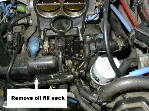 |
| I'm using Taylor-Vertex custom fit Spiro-Pro wires. They look a little bit better than the stock NGKs don't they? I came close to buying MSD wires (which I have on my Mustang), but most people said that they liked the Taylor wires and that the boots were slightly better designed. Can't believe that they were only $26 from Summit Racing. They were cheaper than the 4 Platinum plugs I got... | 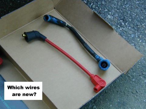 |
| I deinstalled and reinstalled the plugs one by one. This was to keep my dyslexic self from really screwing up. I decided on using NGK Platinums (instead of the non) and 7 leading / 9 trailing plugs. Remember to use a little bit of anti-seize when installing the plugs (on the threads). I once forgot on a motorcycle that I owned and it was a real bitch removing the plugs. | 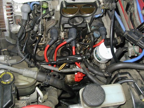 |
| The prior owner had all non-Platinum's and all trailing (9) heat. The plugs don't look too bad, but I felt that given the number of performance mods I've got (downpipe and Racing Beat Intake Duct), I'll keep her closer to stock. When I get my PowerFC, Fluidyne, large SMIC, cat-back, and intake I'll go all 9s. ;) | 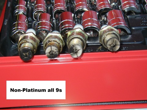 |
| At this point I took a little break. I was pretty amazed by all the parts that had been pulled out of my car! I did my best to wipe off the oil fill neck, throttle body, and intake elbow before the reinstall. BTW, the black plastic cylinder in the middle of the picture actually has two holes, and it gets put hooked onto the 2 bolts that keep the intake elbow on. Don't forget this or it'll be swinging around next to your new wires. | 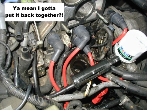 |
| The Taylor wires do like nice don't they? Too bad after she's all beck together you'll never be able to see them again... | 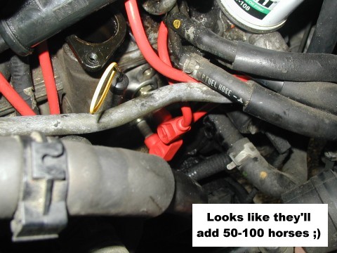 |
| Still more back together shots... | 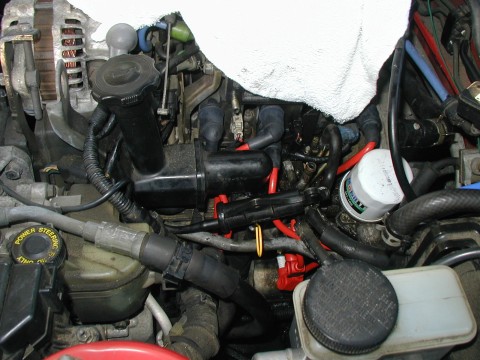 |
| Voila! | 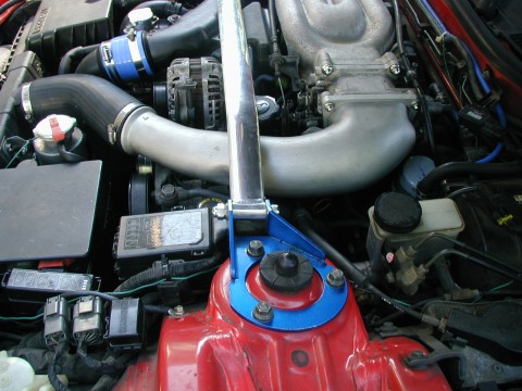 |
| If ya wanna show friends of your handywork after the fact, get prepared to make them do Yoga to see it. | 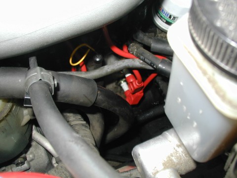 |
_______________
As Joe says, it is easy to do the job from below. I have also included posts on how to do it from above, as the shop manual recommends. --Steve
Date: Thu, 6 Nov 1997 11:34:49 -0800
From: jramos@sunup.Corp.Sun.COM (Joe Ramos)
It is very easy to change the plugs from the bottom through the A-arm using a short ratchet.
The following are instructions provided by Racing Beat for installation of the Ultra "Red Hot" ignition wires. I have copied them as provided except in steps 2 through 5 where the size nut they indicate is dif- ferent than that on my parts. I have included their size in [x] im- mediately following what I have. Also, in step 7 I used different length wire than indicated by them. Again, I put their item in [x] after mine.
*********************************************************************
I11510
INSTALLATION INSTRUCTIONS FOR PART NUMBERS 11510 AND 11511
CAUTION: Attempting to perform this installation task with the engine hot will likely lead to burned flesh!
1. Remove the end of the throttle cable from its attachment on the "constant radius" arm, on which it pulls, by holding the arm in the open position and slipping the barrel-shaped end out of its mounting slot.
2. Remove the clamp on the forward end of the rigid tube leading to the throttle body. Remove the (4) four 10mm [6mm] nuts that retain this rigid tube to the throttle body. It is NOT necessary to dis- connect the small hose at the rear of this rigid tube.
3. Remove the (2) two 12mm [8mm] acorn nuts at the top of the throttle body. Slip the cable clamp off of the rear stud, then re-position the rigid tube (loosened in step 2) over the top of the engine, out of the way of the stock ignition wires.
4. Remove the (2) two 12mm [8mm] chrome acorn nuts from the underside of the throttle body. Gently pull the throttle body off of the studs, exercising caution to keep from destroying the gasket. Ro- tate this throttle body unit up, at the front, to expose the igni- tion coil terminals.
5. Now, loosen the (2) two 10mm [6mm] bolts holding the oil filler neck in place, but do not remove them completely.
6. After detaching the (2) two small hoses attached near the filler cap, the upper portion of the oil filler neck must now be pulled away from the "Trailing Number 1" coil wire to allow its removal.
7. Remove the stock wires and replace with the ULTRA 8MM IGNITION WIRES using the following guide:
WE STRONGLY RECOMMEND REPLACING ONE WIRE AT A TIME TO AVOID ERRORS AND POSSIBLY DAMAGING THE ENGINE.!
        The shortest wire supplied - Trailing Number 1 [2] Coil/Plug
        The second shortest wire   - Trailing [Leading] Number 1 [2]
                                     Coil/Plug
        The second longest wire    - Leading Number 2 Coil/Plug
        The longest wire           - Leading [Trailing] Number 1 Coil/
                                     Plug

        Use the blunt end of a screwdriver to fully push the coil caps
        into place.
8. Reassemble in reverse order.
________________
Date: Fri, 11 Jun 1999 21:04:52 +0000
From: Gordon Monsen (gmonsen@fast.net)
You need one of those small 2-jointed snap-on rachets to do it, but... i just jack up the front end and do it from underneath the car. if you try to do it from the top, you have to remove way too much stuff. doing it from down below, suing the double-jointed small ractchet, its pretty easy and takes less than half an hour. the only problem is that you do the front leading plug pretty much by feel, since you have to contort yourself a bit to get at it.
________________
Joe re-posted the above after Dennis' account of his ordeal (below). I thought I would leave Dennis' here as well, since the more info the better. --Steve
Date: Thu, 6 Nov 1997 11:16:00 -0700 I'm a bit of a do-it-yourselfer, so when I decided that my new-to-me '93
Touring model needed new spark plugs and wires, I didn't hesitate to rush
out and buy some to install myself. "Shouldn't be any tougher than a clutch
job! A ten-minute project" I thought -- I was wrong! Maybe I missed
something obvious to the rest of the world, but I came dangerously close to
losing it over this "minor project!"
So on the fateful day designated for the plugs 'n wires project, I pulled
out my Mazda shop manual (wouldn't have any other, right?), my tools, and
my bright, clean new wires and plugs ready to spend a few rewarding minutes
tending to my car's wants. The manual says to remove the old parts one at a
time, then install the new parts, torque to specs etc. Sounds easy.
Step 1: pop the hood. That's when I realised I might be in trouble, though
exactly _how much_ was still something I could only dimly perceive. I could
barely even _see_ the wires and plugs, much less get at them to yank them
off. So...
Step 2: remove the duct that goes from the intercooler to the throttle
body. Not too difficult, and at least then I could see where everything
was. It still took a while for me to track down which wires woven in with
the other wires and vacuum and coolant hoses were the wires I'd need to
replace. Hmmmm. Maybe a pain, but certainly feasible right?
Step 3: remove old plug and coil wires. I started with the "upper-right"
(#2) wire end (where it goes into the coil) since it is the most
accessible. I like to remove old parts intact, just in case, so I like to
use my hands to remove plug wires. No go here though. I ended up using
plyers as I just couldn't get enough purchase in the cramped quarters to
remove it properly. Oh well, "move on with your life." The spark plug end
was no problemo. The double coil-wires in the center were next, and not too
bad either. I just had to make a mental note of how they all went in so I
could put everything back in the same configuration.
Step 3 (Again? Yes, I still have more work to do here!): remove left (#1)
plug wire from coil. Aaarrrgggghhhhh!!!!!!! There's no way that will ever
come out! It is under the throttle body, and jammed up against the back of
the oil filler tube. After much grunting and straining (ouch... the back of
my knees are starting to get really sore from all this bending over!), I
finally managed to have it mostly pulled off, but not enough for removal.
So I started tearing away at the boot in order to make enough clearance to
pull it out. Still no way. I briefly thought about removing the tube, but
then I'd have to pull out the throttly body too to get at the bolts. Too
much work for a "minor project." I finally used an extra battery J-bolt as
a hook to yank the #1 wire out. Pheww! Looked like a rat gnawed on it (that
actually happened to my previous car... 'nother story), but it's out!
Step 4: Remove old plugs: No problem. Except of course there was so little
room that my ratchet could barely move enough to turn the socket. I was a
little steamed at this point and completely forgot that I own an electric
ratchet. Oh well, it probably would've died right then anyway.
Step 5: Install new plugs. Yippeeee! Fun! I coated each one with a touch of
anti-sieze and torqued to factory specs. Careful not to confuse the
trailing and leading plugs though. I love it when things go that smoothly,
and I get such a warm, contented feeling when I use that beautiful torque
wrench! (Used the smaller lbs/inch one here.)
Step 6: Install new plug and coil wires. Arrgghhh. That's when I realised
that the stupid oil filler tube was still in the way, and there was no way
I'd ever get that #1 wire onto the coil with it in place. Deep breath
(actually a sigh of resignation).
The _real_ step 6: Remove throttle body and oil filler tube (should have
been step 3). Started yanking off the hoses and wires going into the
throttle body. Not laughing any more. It's easy to write "yanking off the
hoses" but it's never as easy as it sounds when those hoses are five years
old and have never been removed from their cramped quarters. And I really
didn't want to use plyers on them. So of course that was another major
hassle that left my hands with numerous small scars. (I'd long since pulled
off my gloves to get better clearance and feel.) But the throttle body
finally came off, and, in short order, the oil filler tube! (Then I think I
just stood there for a while moaning and staring at the engine
compartment... but I don't know for sure as my wife wasn't around to verify
this and I can't remember anything during that short period of time. That's
not really required for step 6/3, but I couldn't help it.)
Step 7: Install new plug and coil wires. For real this time! Went fairly
smoothly too, though the plug ends of the wires don't have a lot of metal
for clipping onto the plugs, so I was never sure that they were seated
properly. Still, it wasn't too bad.
Step 8: Re-install throttle body and oil filler tube. Not bad.
Step 9: Re-install the duct that goes from the intercooler to the throttle
body. Piece of cake.
Step 10: Re-connect all hoses and wires that were supposed to be
re-connected in steps 8 and 9, and remove all the tools lying around in the
engine compartment. Optional: Retrieve the socket and extension that fell
down onto the top of that plastic shroud underneath the engine. Experience
brief panic when you fear that you'll have to pull the shroud off in order
to find the socket and extension.
Step 11: Start engine and test drive. Re-connect that vacuum hose that was
supposed to be re-connected in steps 8, 9 and 10 that is causing your
engine to run like a turn-of-the-century farm tractor.
Now enjoy the pride and satisfaction that comes from knowing that you're
doing everything you can to make sure your car runs in tip-top shape! And,
yes, it _does_ run smoother and stronger with the new plugs and wires.
_________________
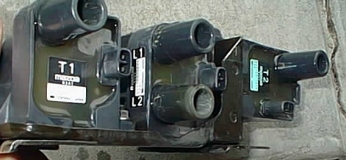
Date: Thu, 20 Nov 97 22:15:44 PST Here is an easy way to remember which wires go to which plugs.
Start counting from the front of the engine to the back. The front rotor
is 1, the back rotor is 2.
The TOP plug is T. The LOWER plug is L.
So looking at the plug side of the engine you have.
Just a simple tip to make hooking those plug wires back up a snap!
________________
Date: Mon, 30 Mar 1998 11:45:37 -0800 (PST) Installing new plugs and wires is a royal pain. I won't bore you with
all the problems I had this weekend, but here are some things to keep
in mind if you do this yourself.
The results:
My old plugs were 33k miles old. I didn't realize how rough the
engine ran until now. The engine is noticably smoother. I certainly
won't wait 33k miles to change plugs again (although I may never do
the wires again!)
__________________
Date: Fri, 31 Jul 1998 18:29:02 -0400 To access the coils, you need to remove the throttle body and oil filler
tube but not the extension manifold (that big aluminum thing). The TB has 2
water lines, be prepared to plug them ASAP when you pull them off. Draining
the coolant isn't really necessary.
________________
Date: Mon, 3 Aug 1998 03:40:39 -0500 Ok, well I spent Sat. afternoon changing the plugs and wires on my '94 Touring.
All told it took me 6 hours of fumbling and three trips to Auto Zone. But
I think I (or you) could do it again in 2 hours with the right info).
The info I found on the web really wasn't very helpful. I've started to write
up a more detailed description of the process to put on the web... but
pictures would really help with that and I've discovered that drawing from
memory is harder than I'd thought.
I'll summarize the important stuff in this email.
You need:
Cutting to the chase, here's what I found:
You can change the plugs and wires from the top of the car by removing
the rigid air intake tube and by loosening (but not completely removing) the
oil filler tube. There are a couple of things that require some creativity,
but nothing impossible.
Important tip - Make a flat hook with the coat hanger and use it to
pull off the coil end boots of the wires. With the coat hanger it's easy,
without it's impossible.
Now, the oil filler tube is your enemy... you must defeat it.
The oil filler tube has *three* bolts (not two as one FAQ noted). The first
is obvious. The 2nd one corresponds and it is a major pain, as it's behind
the tube itself. It seems impossible at first, but you can get it if you
remove two center coil plugs first. I think you also may want to disconnect
an electrical connector for a cable that's in the way. With the coil plugs
removed you have room to get the 10mm crescent wrench back there and one
painful notch at a time loosen the bolt. I would *not* remove this one all
the way... it's not necessary.
The third bold is a 10mm that's to the left of the other two and under the
main body of the oil filler. You can't see it, but you can feel it. You can
see the welded nut on the opposite side... (for a while I thought *that* was
the one I had to reach... Ug!) Use a 10mm wrachet on an extension... If you
can't get the whole wratchet in there (steering fluid hose in the way) then
try putting just the extension on and using the vise grip to loosen the bolt.
Don't take it off... just loosen everything so that you can pull the
oil filler body away from the #1 plug coil by an inch or so... enough to weasel
off the plug and get another one on. Note: you won't really have enough room,
but you can do it.
My Magnecor info says to "burp" the wire boots using a coat hanger, but I
had no success with this... hard to tell if it was working. I have to say
that I was not thrilled with how the boots for all the wires fit. They didn't
seem as snug as the stock ones (but maybe after 15K miles they will?)
It also helped to remove the oil filter to get to the #4 coil boot.
Oh, and the two ostensible plug/coil wire maps that I found on the other
instruction web site were completely useless: one contained no info and the
other was incomprehensibly muddled. For the record, here it is (the numbers
are arbitrary - just match them):
I think that's it.
My symptoms were jerking / weak under WOT over the top half of the rev range.
The new wires/plugs seem to have fixed the problem.
_______________
Date: Mon, 3 Aug 1998 12:57:56 -0600 To make the boots slip on and off easier, I spray them with
7% (the good stuff) silicone spray before putting them on. It's
good for the boots, repells water, and makes the job MUCH easier.
Course if you get too much on the outside of the boots they will
be slippery.
________________
Date: Mon, 3 Aug 1998 18:02:58 -0700 The only thing I can add, is that instead of removing the oil filler pipe, I
removed the coil to remove/re-attach the plug wire to.
The coil seemed like a better choice for me.
_________________
Date: Sat, 9 Jan 1999 10:58:00 -0800 >Can somebody please tell me what the factory specs are for tightening the Page G-18 of the good book says, 13-17 N*m {1.3-1.8 kgf*m, 9.5-13 ft*lbf}
________________
Date: Mon, 15 Mar 1999 12:07:38 -0600 Editor's comment: Steve's note is an add-on for Rob's instructions. --Steve
Here are a couple things you may want to footnote with the
instructions. Or maybe not... :-)
Step 3 - I removed the bolt holding the boost control bracket, which made
swinging the rigid tube over the top of the engine a lot easier.
Step 4 - To remove the throttle body I HAD to disconnect the coolant hose
directly below the throttle body. A definite pain to get off and on.
Step 5 - I had to move the filler neck to remove the front plug wire. On
my car there is a 3rd bolt holding the filler neck in place, under the
horizontal part of the removable neck. Another pain to get to. Since I had
all the bolts loose I figured I might as well remove the neck completely.
It did make access easier, but when I went to bolt it back on I couldn't get
the rear vertical bolt to line up and start threading. I had to remove a
coil wire to get the bolt started. Then the wire was interesting to put
back on. Hmm, which came first, the wire or the bolt???
Step 8 - I was VERY careful removing the throttle body to try and keep
from breaking the gasket. The gasket looked fine till I was putting the
throttle body back on, when it tore. Next time I will set the gasket aside
while working, and place it on the intake side when putting it together. On
the bright side, the broken gasket hasn't affected the idle much more than
50 RPM, and that might just be the colder weather today. So I guess I'll
drive it until the new gasket gets here.
BTW, the best tool I've gotten in a long time is a hose remover. Like a
reverse pliers, squeeze the handle and the thin V-notched jaws separate. I
think it's a MAC tool. Makes removing a lot of fuel lines, ect a lot
easier.
_________________
Date: Mon, 15 Mar 1999 14:03:30 -0500 There is a newer revision of the throttle body gasket. All metal design.
The rip you have will get worse as it works its way loose over time.
I would suggest going to get the new one, I think it was 18 dollars at the
dealership.
_________________
Date: Mon, 10 May 1999 23:16:48 -0400 Do it from the top & get the proper tools. Stubby socket
wrench with swivel head & deep socket sparkplug socket
(not with the rubber stuff to hold the plug). Break it
loose and once started, remove by had. Screw in new plug
by hand and then tighten. USE ANTISEEZE on all plug
treads. Do one plug at a time (impossible to get the
wire confused this way)
_________________
Spencer Hutchings used White Out dots to idiot-proof the
plug wire repalcement process:
Date: Thu, 18 Dec 97 13:40:37 -0500 I recently had a Hi-6 installed in my 94 R2 and I love it. I strongly
considered the Jacobs given the sales pitch from both Jacobs and Rotary
Performance, however, I am now so glad that I went Hi-6. I have sent some
private e-mails to others on this subject but have not posted to the list
yet. I think its time. What I have attached to this note is relevant
copy of several messages ...
BTW, I used Brook's instructions
for installing the Crane with one
addition: We hooked up the blue wire to the thin red wire. It rocks. I
have to send thanks to Mark Schroder of Precision Imports, Mark turned me
on to the blue wire connection. My car would not run without this
connection (please do not ask me why, I do not know and neither does
anyone from Crane).
Thanks to Brad
Barber as well for letting me be the guinea pig once again for another RX7
modification. The Crane seems to be doing wonders on his car as well, 355
rear wheel horsepower, what a beast.
_____________
Date: Wed, 28 Mar 2001 17:17:35 -0800 (PST) If on leading, it should be "set" to 4-cylinder mode - i.e. thin, light
blue wire to +12VDC.
If you have the digital wheels set to defeat multi-spark mode (someone's
webpage recommends to do this), then it doesn't matter if the thin, light
blue wire is connected to anything; the cylinder select wire is basically
to control multi-spark mode on/off and RPM limit (note: the RPM limited
doesn't really do anything if you're running the HI-6 solely on the
leading).
_____________
Date: Tue, 13 Oct 1998 18:55:11 -0500 Crane Cams Hi-6 install:
The fat red wire connects to the battery.
The small red wire connectd to +12 (one of the two leads from the ignitor
that used to go to the leading coil)
The white wire should go to the trigger lead (the other wire from the
ignitor that used to go to the leading coil)
The small blue wire should be spliced to the small red wire.
The Gray cable with two wires inside should be taped up and not used.
The black cable with two wires goes to the coil.
_______________
Date: Sun, 30 May 1999 10:03:45 -0400 "Friends don"t let friends Short Circuit their Crane installation"
Having waited 3 weeks to get my car up and running again after royally
screwing up my Crane Hi-6 installation, I offer the following tips and
warnings to add and emphasize to the otherwise thorough Brooks Weisblat
How-to.
1. TIP- The coil harness that needs to be spliced into is only 1 foot
long. Make yourself a favor and take it out of the car in order
facilitate the wiring work to be done.
2. WARNING- Earlier harnesses ("93) have 1 of the wires that need to be
intercepted which is similar to coaxial wire. Brooks makes mention of
this wire and cautions to peel back the (grounded) sheathing of this
wire far enough, making sure that it's not crimped with the wire
connection. This the part that I screwed up on. I ended up shorting the
whole installlation... coil harness melted, connectors to Leading coil
fused together, harness coil connector fused to the main harness coil
connector, and a burnt Leading coil(s).
3. TIP- Instead of hardwiring the Crane wires into the car's harness,
use connectors that allow you to take the Crane out and reconnect the
stock wiring back together if the unit goes bad or whatever. I ended up
using Weatherpack connectors. (Thanks Brad Barber)
________________
Date: 20 Jul 2000 11:18:59 -0700 Yes, you connect the blue wire
Connect the power to the battery or 120A fuse box
________________
Date: Thu, 20 Jul 2000 20:33:30 -0400 Did you set the 2 dials on the HI-6? you need to set them to 0 and 1 for
multi-spark. Don't quote me on the dial setting, its been so long, so look
it up in the Crane manual that accompanied your ignition amplifier.
________________
Date: Fri, 24 Mar 2000 22:54:01 -0800 A look at the factory wiring harness diagram in my Workshop Manual (page
Z-28) shows that those black and red wires are equivalent. I suggest you
connect to the one that is in the leading coil connector because that is
where the other wire you need to cut is.
Though I have yet to do it, I bought a bunch of Weatherpack connectors
to use when I install my HI-6. I am thinking that I will cut the leading
coil connector off the little harness and install mating connectors on
the ends. That way, I can hook it back up like stock if I want to get
rid of the HI-6 for any reason. I will install the appropriate
connectors on the HI-6 so that I can plug it in.
Here is a diagram, where a 'F<' indicates a female connector, and a ' Watch out for the shielding on the yellow and blue wire that needs to be
spliced here. I guess you need to peel back the shielding and be sure
that it is NOT making contact with the wire in the center. The HI-6
installation instructions
may be helpful for this part.
_____________
Date: Thu, 17 Jun 1999 20:55:53 EDT Check out "Ignition" on Paul Yaw's website. He describes how to install an
MSD on a rotary engine:
________________
Date: Fri, 12 Nov 1999 11:11:57 -0500 On the 2nd gen it's as follows, I don't know how the coils are set up on
a 3rd gen.
_________________
Date: Fri, 12 Nov 1999 12:05:25 -0500,BR>
From: Nick (nsaveski@home.com)
>The part that I am confused on is which wire is the coil + and which is the coil?
Like I said, I don't know how it's set up on the 3rd, but
on the [2] the leading (and trailings) are in coil 'packs' which is, the
coil and ignitor are put together in one piece, roughly.
Thing is, they're actually separate. There's a plastic cover that says
'L1 L2' on it, right near the plug wire terminals. This (on 2nd gens)
should pop off, and underneath there should be two wired screwed into
the coil, coming from the ignitor.
They should be marked somehow, coil+ and - will be the small posts on
the coil, and ignitor+ and - will be the two wires. I make little
adapters that I screwed on and covered with shrink tubing and screwed
onto the coil posts so that I didn't have to butcher anything. Works
good.
Remember, this is all for the FC. :)
_________________
Date: Mon, 05 Jun 2000 20:00:07 -0500 There are a lot of people running around with Crane,
Jacobs, and MSD ignition upgrades. Based on my latest dyno
trip, I have some possibly interesting findings to share.
first, when we hooked up an oscilloscope to the trigger
wheel pickups, we saw that the trigger wheel was so close to
the pickups that there was interference from the trailing
signal to the leading signal. This caused the square wave
for the leading signal to take a very different (not square
at all) form. The rising edge ascended way higher than it
should have and oscillated a lot as it came down over the
period where it should have been perfectly horizontal. When
it fell, it decayed away smoothly, though it was a curve and
not a vertical line falling to zero. With the haltech you
can set the ignition to occur on the rising or falling edge
of the signal. when set to trigger on the rising edge, the
car started, idled and ran well to 3-4000 rpm and above that
it broke up intolerably. Set to trigger on the falling
edge, the car was very hard to start, idle and a bit rough
until about 3000 rpm. Then it ran like a champ to 10,000
rpm.
Now, the reason it wouldn't start when set to trigger on the
falling edge is that there is 3 ms of dwell time (the higher
horizontal period of the square wave) and this delay
probably results in 15-20 degrees of advance over what was
set by the computer. So, at higher rpm it liked it, but at
lower rpm and idle it wouldn't run well with so much
advance. Set to trigger on the rising edge, it would start
well, but the interference from the trailing signal would
cause the break-up at higher rpm where the shape and height
of the rising edge would confuse the ignition.
The two interesting things here for the list and those using
aftermarket ignitions are: (1) the MSD and Crane, if not
the Jacobs, is that they have built-in dwell times of about
2-3ms and (2) how might the trigger wheel's proximity to the
pickups be effecting ignition at higher rpm. The first
issue has to do with what the stock or aftermarket
ecus/computers see and do to timing relative to this delay.
with my haltech, i have to set whether it triggers on rising
or falling. If i set to rising, the timing i have set with
the haltech is what i get. if i set it as falling, my
actual timing is 15-20 degrees more advanced than what the
haltech says it is. Soooo, if the efi/pms or stock computer
is set to trigger on the falling edge and you are using an
aftermarket ignition, i strongly suspect that you are using
timing that may be far more advanced than you think. anyone
know where the stock computer is set to fire?
Second, the problem with the trigger wheel being too close
to the pickups may be causing some of the "break-up" I keep
hearing about from some guys over 5,000 rpm. I would think
it makes sense to check this out at your local mechanics the
next time you get a chance. Have him hook up an
oscilloscope to the pickups and see what's going on. Dave
Barninger (KD Rotary, Allentown, PA) bought an oscilloscope
and wideband lambda meter and is going to be able to not
only check this, but tune cars better. Check to make sure
your mechanic has an oscilloscope and check this out.
Moving out the trigger wheel to 80/1000ths (max value) could
help reduce high rpm break-up.
Date: Mon, 3 Apr 2000 14:02:54 -0400 That is funny I just did it yesterday. But you have to remember to minus the
resistance of the leads for the meter. For example if you touch your meters
leads together and get .4 you need to minus that from you reading because
you want the resistance of just the coil not the coil and the leads from
your meter.
Date: Tue, 20 Mar 2001 21:41:42 -0500 (EST) I thought this question had been answered the last time you asked,
otherwise I would have answered the first time. I guess it slipped
through.
You cannot change the timing without modifying the ECU. Your original
post said, if I recall correctly, that a friend of yours told you that you
needed to adjust your timing because you were running rich. I don't know
why he would think that running rich would be mediated in any way by a
timing adjustment. If your timing was off that much, the least of your
worries would be the gas smell, the car would not run very well.
I can't comment on the reason your car is running rich other than to say
that you are barking up the wrong tree. I'm assuming that your engine
check light isn't on. More information might be helpful. Is there
anything other than an exhaust smell that leads you to believe you are
running rich? What are your mileage and driving habits like? Is your air
pump connected? If I understand correctly, a clogged intake filter will
cause you to run rich but only at WOT when static maps are used. Are you
sure the smell is gas? Did anything change before the smell started, or
was it just always that way? Have you looked at your plugs to see if they
can tell you anything?
Forget about the timing, there are a lot of things that it might be and
that isn't one of them.
[Mail me]
[To Lightning home]
[To my home page]
[Copyright Notice]
From: Dennis S Pedersen
From: John Lockwood
        T1              T2
        L1              L2
From: Bill Geiger
From: "Houseman, Carl W. x1323"
From: Pat
Replacement plugs -
    I got mine from my Mazda dealer
    cost: 4 plugs (2 leading, 2 trailing) about $32

Replacement wires -
    I used Magnecor 10mm wires per someone's recommendation
    cost: ordered from Mazdatrix about $50

- - 10mm wratchet with about a 2+ inch extension.
- - 10mm crescent wrench (for one hard job)
- - A wire coat hanger (very important!)
- - Plyers
- - Phillips and a flat head screw drivers
- - Possibly a vise grip plyers
- - A light of some kind
- - Some towels to wipe grease off your hands and help you grip and turn
   loosened bolts.
            coil 1     coil 2      coil4

                       coil 3

  (trailing) plug 1                plug 4 (trailing)

  (leading)  plug 2                plug 3 (leading)
From: David Beale
From: "Derek Vanditmars"
From: "Derek Vanditmars" (dvandit@istar.ca)
>spark plugs.
From: "Stover, Steve" (Steve.Stover@ies.msfc.nasa.gov)
From: skight@enterprise.reliacom.com
From: Sandy Linthicum (sandy_linthicum@mindspring.com)

Ignition Coils
From: "Kyle Krutilek" (kekr@lubrizol.com)
From: Ted Koseki (f8ldzz@yahoo.com)
From: Quinton McCombs (quintonm@bellsouth.net)
From: David Ieroncig (Rx7@Rocketship.com)
From: Steve OBrien (poweraxel@peoplepc.com)
> I recently purchased a HI-6.  I'm almost finished with the install
> (haven't had much time this week).  I just thought I'd ask a few questions
> before firing it up this evening.
>
> Those who have installed a new one in the past 6 months or so.. did
> you have to connect the blue wire?  Brooks' site said he didn't have to, but
> some people with newer ones have.  Mine is a newer black one.
> Also.  Is a good place to connect the power to the back of the
> smaller (battery) fuse box (I used one of the bolts that is closer to the
> tire).  I think this is after the main 120A fuse, but I'm not certain.  Do I
> need to connect it to the other side (closer to the engine)?  Is it wise to
> add a fuse to the power?  What size? (didn't see anything in the manual
> about fusing it)
From: Wael El-Dasher (wael.el-dasher@efini.net)
> I just finished installing a HI-6 earlier.  The car ran like crap
> and would barely idle.  So I hooked the blue wire to the thin red wire (for
> 4 cylinder instead of 8).  No change.  So I bypassed the crane.  No change.
> So I disconnected the J&S harness.  No change.  I conclude my leadings
> aren't firing.  I recheck the plug wires.  I check the connectors I in for
> the HI-6.  I can't find anything wrong with the wiring.
> I could rule out either the plug wires OR the coil wiring if I had a
> way to test if the coil is firing - if the coil is firing, the problem lies
> in my plugs or wires, if the coil is not firing, then I have a bad
> connection from the stock coil harness.
From: Max Cooper (max@maxcooper.com)
Subject: Re: (rx7) [3] Jacobs Rotary Pak wiring help
From: Xanthius@aol.com
From: Nick (nsaveski@home.com)
Coil+ > Orange
Coil- > Black

Ignitor+ > Red
Ignitor- > White

Thick Black > Battery -
Thick Red > Battery +

Tach output optional
Magnetic pickup is NOT used.
From: Gordon Monsen (gmonsen@fast.net)
Subject: (rx7) [3] thoughts on timing with ignition upgrades
Ignition Coil Testing
From: "Karagiannis, Demetrios Mr ODCSINT/GD" (Demetrios.Karagiannis@hqda.army.mil)
Subject: RE: (rx7) [3] Testing Ignition Coils
>...I would test the ignition coils.  The shop manual says that the
>resistance across the terminals should be "UNDER 1 Ohm" to be within spec.
>I measured exactly 1.0 Ohm resistance for both of my trailing coils.  The
>leading coil was 0.6 Ohms.  Since I measured 1.0 Ohm on both the leading
>coils, they are technically out of spec, but juuuuusst barely.  I'd hate to
>replace the coils if there is no need to do so. Does anyone have any
>experience with this?  Should I replace them or not?  Any opinions?
Timing Adjustment
From: Shane Baker (sbaker@null.net)
> Called couple of places today to see how much it would cost me to adjust my
> timing. Some of them said there is no such thing on RX7. They said that the
> ECU adjusts it automatically. Can anyone confirm this? And if this is true,
> why is my idle so rich and the freaking exhaust smells like a damn chemistry
> lab?